You are viewing a javascript disabled version of the site. Please enable JavaScript for this site to function properly.
Go to headerGo to navigationGo to searchGo to contentsGo to footer
Go to chapter navigation

Figure 20.1
Blood bottles.

Figure 20.5
Thermoluminescent dosimeter (TLD) badge.

Figure 20.9
Ultrasound machine and probe.
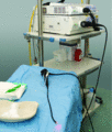
Figure 20.13
Video stack.

Figure 20.17
Family tree or pedigree.
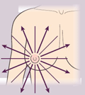
Figure 16b
Radial spoke pattern.
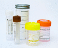
Figure 20.2
Specimen pots.

Figure 20.6
Hand and foot radiation monitor. Source : Dougherty and Lister ( ).

Figure 20.10
Example of TRUS biopsy equipment.

Figure 20.14
Male internal bladder structure. Source : Adapted from Tortora and Derrickson (2011). Reproduced with permission of John Wiley & Sons.
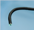
Figure 19a
Cystoscope deflection.
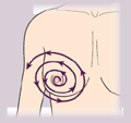
Figure 16c
Concentric circular pattern.
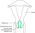
Figure 20.3
The cervix. Source : Dougherty and Lister ( ).

Figure 20.7
The prostate and its zones. Source : Adapted from Tortora and Derrickson (2011). Reproduced with permission of John Wiley & Sons.

Figure 20.11
(a) Female urinary system. (b) Male urinary system. Source : Adapted from Tortora and Derrickson (2011). Reproduced with permission of John Wiley & S...
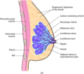
Figure 20.15
(a) Female breast (sagittal section). (b) Female breast (anterior view, partially sectioned). Source : Adapted from Tortora and Derrickson (2011). Re...
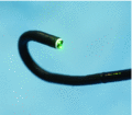
Figure 19b
Cystoscope inflection.

Figure 15
Biopsy site skin stretched.
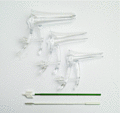
Figure 20.4
Vaginal specula and cervical broom.
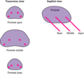
Figure 20.8
Prostate core biopsy.

Figure 20.12
Flexible cystoscope.

Figure 20.16
Biopsy device and needle.
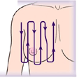
Figure 16a
Vertical pattern.

Figure 19
Punch biopsy technique.


